Virtual Local Area Networks (VLANs)
Virtual Local Area Networks, or VLANs, are a very simple concept that has been very poorly defined by the industry.
This article will explain VLANs from a practical perspective. It will be framed around the two major functions of VLANs, and then concluded with another equally poorly defined concept, the Native VLAN.
Finally, at the end of the article is a two question comprehension challenge – if you can successfully answer these two questions, then you can consider yourself to fully understand the concept of VLANs — the topic of configuring VLANswill be covered in another article.
Two Major Functions of VLANs
Below is a network with three different physical switches. The switches facilitate communication within networks, and the Routers facilitate communication between networks.
Each switch above independently performs the four functions of switch.
If each of these switches have 24 ports and only two are in use, then 22 ports are left wasted on each switch. Moreover, what if you need to replicate this network elsewhere and you do not have three physical switches to accommodate?
That is where the first major function of a VLAN comes into play: A VLAN allows you to take one physical switch, and break it up into smaller mini-switches.
Breaking up one Physical Switch into multiple Virtual Switches
Consider each circle on the switch below as its own mini-switch. Each of these mini-switches, or virtual switches, operate completely independent from the others — exactly as they would had there been three different physical switches.
Traffic flow through this topology operates exactly as it did in the topology above it (with three separate physical switches).
Each virtual switch, or VLAN, is simply a number assigned to each switch port. For example, the two switch ports in the red mini-switch might be assigned to VLAN #10. The two ports in the orange mini-switch might be assigned to VLAN #20. And lastly the two switch ports in the blue mini-switch might be assigned to VLAN #30.
If a port is not explicitly assigned a VLAN number, it resides in the default VLAN, which has a VLAN number of 1.
Traffic arriving on a switch port assigned to VLAN #10 will only ever be forwarded out another switch port that belongs to VLAN #10 – a switch will never allow traffic to cross a VLAN boundary. Again, each VLAN operates as if it were a completely separate physical switch.
In the first illustration, traffic from the red switch cannot magically appear on the orange switch without first passing through a router. Similarly, in the second illustration, traffic in VLAN #10 cannot magically appear on VLAN #20 without also passing through a router.
Each of the VLANs also maintain their own, independent, MAC address table. If Host A sends a frame with a destination MAC address of Host B, that frame would still be flooded solely within the switch ports in VLAN #10.
Ultimately, assigning different ports to different VLANs allows you to re-use a single physical switch for multiple purposes. This is the first major function of a VLAN.
But that isn’t all VLANs allow you to do. The second major function is VLANs allow you to extend the smaller Virtual switches across multiple Physical switches.
Extending Virtual Switches across multiple Physical Switches
To illustrate this point, we will expand the topology above with an additional physical switch and two additional hosts:
Notice how a VLAN# 10 and VLAN# 30 have been extended onto a second switch. This enables Host A and Host C to exist in the same VLAN, despite being connected to different physical switches located in potentially different areas.
The primary benefit of extending a VLAN to different physical switches is that the Layer 2 topology no longer has to be tied to the Physical Topology. A single VLAN can span across multiple rooms, floors, or office buildings.
Each connected switch port in the topology above is a member of only a single VLAN. This is referred to as an Accessport. An Access port is a switch port that is a member of only one VLAN.
Whenever the switch receives any traffic on an Access port, it accepts the traffic onto the configured VLAN.
In order to extend a VLAN to the second switch, a connection is made between one Access port on both switches foreach VLAN. While functional, this strategy does not scale. Imagine if our topology was using ten VLANs, on a 24 port switch nearly half of the ports would be taken up by the inter-switch links.
Instead, there is a mechanism which allows a single switch port to carry traffic from multiple VLANs. This is referred to as a Trunk port. A Trunk port is a switch port that carries traffic for multiple VLANs.
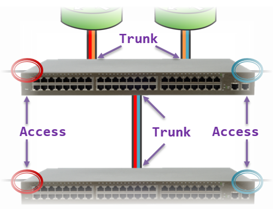 We can use Trunk ports to reduce the amount of switch ports required for the topology above. This enables us to leave more ports available to add hosts to the network in the future.
This physical topology operates (logically) identically to the illustration above it, but requires far fewer switch ports.
We were able to use a total of four Trunk ports (across both switches) to replace eight different Access ports in the prior illustration.
Typically, switch ports connected to end-host devices are configured as Access ports (e.g., workstations, printers, servers). Conversely, switch ports connected to other network devices are configured as Trunk ports (e.g., other switches, routers). We will uncover the reason for this later in this article.
Tagged Ports and Untagged Ports
A Trunk port on a switch can receive traffic for more than one VLAN. For example, in the illustration above, the link between the two switches is carrying traffic for both VLAN 10 and VLAN 30.
But in both cases, the traffic is leaving one switch as a series of 1s and 0s, and arriving on the other switch as a series of 1s and 0s. Which begs the question, how will the receiving switch determine which 1s and 0s belong to VLAN #10, and which 1s and 0s belong to VLAN #30?
To account for this, whenever a Switch is forwarding traffic out a Trunk port, it adds to that traffic a tag to indicate to the other end what VLAN that traffic belongs to. This allows the receiving switch to read the VLAN tag in order to determine what VLAN the incoming traffic should be associated to.
An Access port, by comparison, can only ever carry or receive traffic for a single VLAN. Therefore, there is no need to add a VLAN Tag to traffic leaving an Access port.
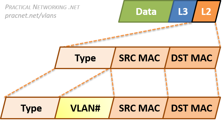 Since VLANs are a Layer 2 technology, the VLAN Tag is inserted within the Layer 2 header. The standard Layer 2 header in modern networks is the Ethernet header, which has three fields: Destination MAC Address, Source MAC Address, and Type.
When an Ethernet frame is exiting a Trunk port, the switch will insert a VLAN Tag between the Source MAC address and the Type fields.
This allows the receiving switch to associate the frame with the appropriate VLAN.
To summarize, the final topology with traffic traveling between Host C and Host D through Access ports and Trunk ports will look like this:
The physical topology above will work exactly like the logical topology below. The hosts will not know whether they are going through two physical switches (or three or four), or what VLANs they are in. They operate exactly as they would in any situation which involves moving packets through a network.
Access Ports and End-Host Devices
Earlier we mentioned Access ports typically face end-host devices like workstations or printers or servers. Part of the reason for this is that switches do not add a VLAN tag when sending traffic out an Access port.
Most end-host devices do not understand the concepts of VLANs. In fact, if they received frames with a VLAN tag inserted in the middle of the Ethernet header, they are likely to drop them under the assumption that they were malformed frames.
Of course, understanding the concepts of VLANs is merely a matter of installing the right software or software patch, but imagine the overhead of requiring every user on your network to both install the software patch, and configure their devices to send the appropriate VLAN tag.
It is much better for the network administrator to configure and concern themselves with VLANs, and for the end-host devices to remain blissfully ignorant of what VLAN they are in, or even whether VLANs are being utilized at all.
Terminology
Finally, a quick note on terminology. The terms Access port and Trunk port are usually associated with the Cisco world. But VLANs are an open standard, therefore other vendors are able to implement VLANs as well.
What Cisco calls a Trunk port (i.e., a switch port that carries traffic for more than one VLAN), other vendors refer to as a Tagged port – referring to the addition of a VLAN tag to all traffic leaving such a port.
What Cisco calls an Access port (i.e., a switch port that carries traffic for only one VLAN), other vendors refer to as anUntagged port – referring to the traffic leaving the switch port without a VLAN tag.
These terms are not exhaustive, there are some vendors that may yet use other terminology, other vendors may even mix and match these terms. Regardless of the terminology used, all the concepts discussed above still apply.
802.1q VLAN Tag
VLAN tags requires adding and removing bits to Ethernet frames. The specific sequence of bits to add is governed by an open standard, which allow any vendor to implement VLANs on their devices.
The exact format of the VLAN Tag is governed by the 802.1q standard. This is an open, IEEE standard which is the ubiquitous method of VLAN tagging in use today.
To demonstrate exactly how the VLAN Tag modifies a packet, take a look at the packet capture below of the same frame before and after it exits a Trunk port.
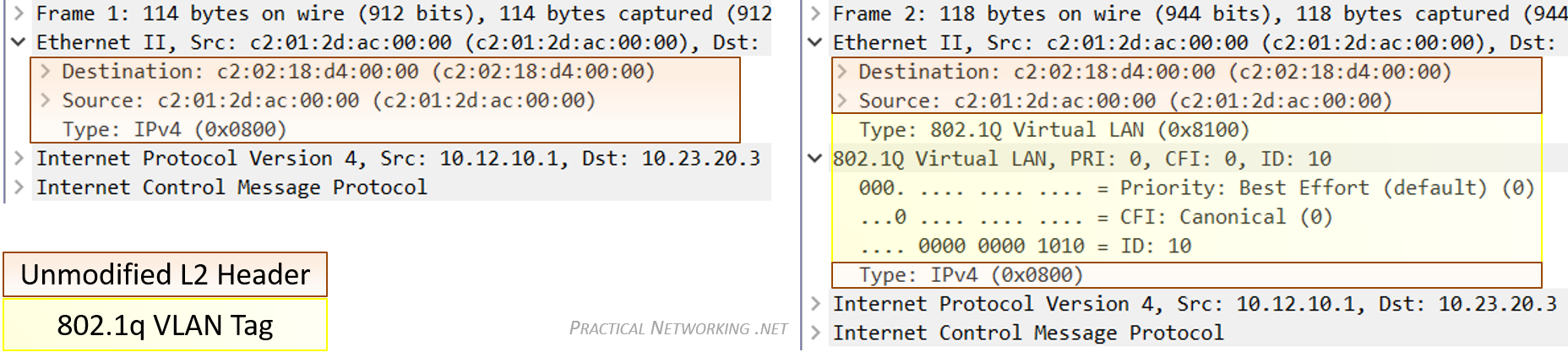
The portion of the frame highlighted in yellow is the added VLAN tag. Notice it is inserted between the Source MAC address and Type field of the original Ethernet header.
You can view this capture yourself in Cloudshark, or you can download the capture file and open it in Wireshark.
No other modification to the frame or its payload is made by the addition or removal of the VLAN tag. That said, since even the slight modification displayed above is made, adding and removing the VLAN tag also involves recalculating the CRC — which is a simple hash algorithm devised to detect transmissions errors on the wire.
There is an older method of VLAN tagging which is a closed, Cisco proprietary method. This method was called Inter-Switch Link, or ISL. ISL fully encapsulated the L2 frame in a new header which included the VLAN identification number.
But these days, even newer Cisco products do not support ISL, as the entire industry has moved to the superior, open standard of 802.1q.
Native VLAN
There is one final concept associated with VLANs that often brings confusion. That is the concept of the Native VLAN.
The Native VLAN is the answer to how a switch processes traffic it receives on a Trunk port which does not contain a VLAN Tag.
Without the tag, the switch will not know what VLAN the traffic belongs to, therefore the switch associates the untagged traffic with what is configured as the Native VLAN. Essentially, the Native VLAN is the VLAN that any received untagged traffic gets assigned to on a Trunk port.
Additionally, any traffic the switch forwards out a Trunk port that is associated with the Native VLAN is forwardedwithout a VLAN Tag.
The Native VLAN can be configured on any Trunk port. If the Native VLAN is not explicitly designated on a Trunk port, the default configuration of VLAN #1 is used.
That being said, it is crucially important that both sides of a Trunk port are configured with the same Native VLAN. This illustration explains why:
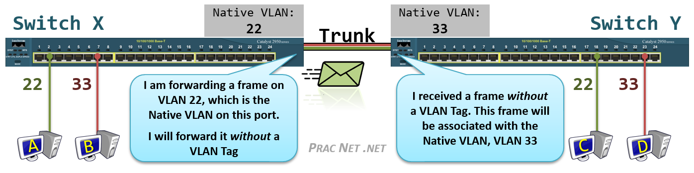
Above we have four Hosts (A, B, C, D) all connected to Access Ports in VLAN #22 or VLAN #33, and Switch X and Switch Y connected to each other with a Trunk port.
Host A is attempting to send a frame to Host C. When it arrives on the switch, Switch X associates the traffic with VLAN #22. When the frame is forwarded out Switch X’s Trunk port, no tag is added since the Native VLAN for the Trunk Port on Switch X is also VLAN #22.
But when the frame arrives on Switch Y without a tag, Switch Y has no way of knowing the traffic should belong toVLAN #22. All it can do is associated the untagged traffic with what Switch Y’s Trunk port has configured as the Native VLAN, which in the case is VLAN #33.
Since Switch Y will never allow VLAN #33 traffic to exit a VLAN #22 port, Host C will never get this traffic. Even worse, due to a Switch’s flooding behavior, Host D might inadvertently get the traffic that was destined to Host C.
Finally, it should be noted that the Native VLAN is an 802.1q feature. The antiquated tagging mechanism of ISL simply dropped traffic receive on a Trunk port that did not include the ISL tag. Also, remember that the Native VLAN concept only applies to Trunk ports — traffic leaving and arriving on an Access port is always expected to be untagged.
VLAN Comprehension Challenge
To test yourself to see if you fully understand how VLANs work, there is a simple challenge we can offer.
Below is a (poorly) configured topology, featuring five switches and twelve hosts. Each switch port is configured as either an Access port in the displayed VLAN, or a Trunk Port with the Native VLAN displayed.
The challenge is to answer just these two simple questions:
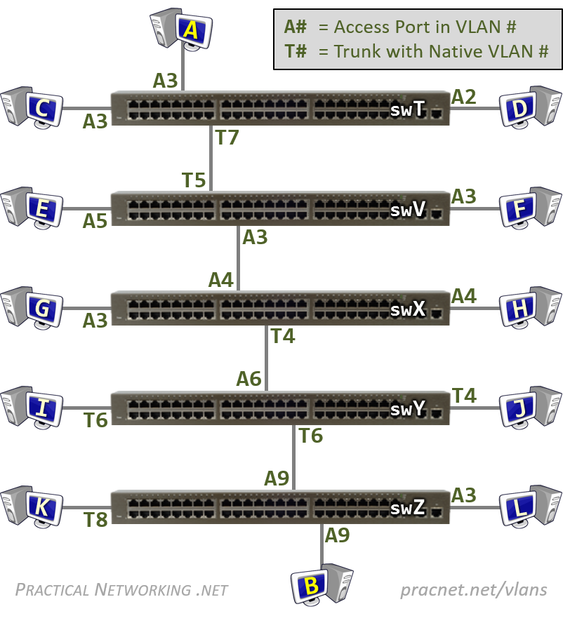
Question #1: If Host A sends a frame to Host B, will Host B receive it?
Question #2: If Host A sends a Broadcast, which hosts will receive it?
The answers and an explanation are provided below.
Remember, the goal isn’t simply to get the answer right, but to be able to understand why. If you can explain the answers to both of these questions to someone else, then you know you will have mastered the concept of VLANs.